
34
Extrusion International 1/2017
PERIPHERAL EQUIPMENT
A new-generation coextrusion feedblock
from
Nordson
Corporation
enables
processors of film, sheet, and coatings
to fine-tune individual layers as well as
accommodate changes in layer ratio, and to
adjust the tuning systemwithout removing
the feedblock from the production line.
G. Iuliano, business development manager for polymer dies. “This
provides more area for tuning layer thickness uniformity and thus
makes possible more accurate and effective tuning. In addition,
changing the position of the profile bars dramatically changes the
result, allowing for significant process refinements to be made on-
the-fly.”
The positioning of the profile bars with respect to the combining
point is adjusted by rotating the profiling actuators. This is accom-
plished by turning nuts on the outside of the feedblock in accor-
dance with a position indicator and does not entail stopping pro-
duction.
The profile bars are available with various surface configurations,
including a standard bar with a uniform raised surface and others
designed to correct such issues as heavy end flow, heavy center
flow, or “M” or “W” patterns. The bars are installed in dovetail
grooves in the surface of the profiling actuators. A cover plate in
the feedblock provides access for replacing one set of bars with
another. Adjusting the profiling actuators in the Ultraflow V-T
feedblock makes it possible to influence the distribution of a par-
ticular layer. If further adjustment is necessary, one can replace the
profile bars by briefly stopping production, without having to re-
move the feedblock from the extrusion line. Nordson will specify
a feedblock whose flow channel differs in size from the standard
4 in. (100 mm), with widths available from 2 in. (50 mm) up to 7 in.
(180 mm) depending on the width of the product to be extruded.
Larger volume feedblock channels reduce the shear stress levels at
the layer interfaces and a wider feedblock channel contributes to a
more consistently on-specification product. In the case of a 100-in.
(2,540-mm) die, for example, the spreading ratio is 25:1 for a 4-in.
feedblock channel but only about 14:1 for a 7-in. channel.
As in the Ultraflow V feedblock, the combining planes in the new
Ultraflow V-T system combine polymers in a parallel-path manner,
achieving optimal layer ratio stability throughout the structure.
Their ability to be adjusted ‘on the fly’ increases uptime and allows
for greater end-product versatility.
The Ultraflow V-T feedblock is available with Nordson’s optional
selector spool that allows the layer sequence to be pre-arranged
upstream of the combining point, without removing the feedblock
from the production line.
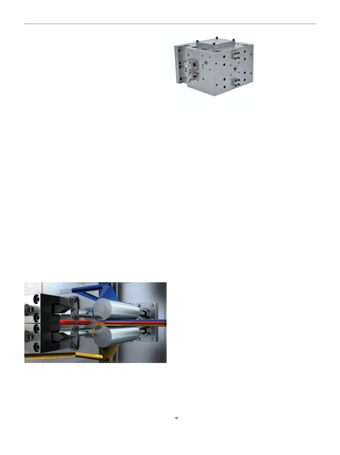
A feedblock combines melt streams from separate extruders into
a multi-layer “sandwich” that the extrusion die subsequently dis-
tributes to target product width. The new EDI™ Ultraflow™ V-T
feedblock has separate devices for fine-tuning layer stability and
thickness uniformity, and both are capable of being adjusted with-
out stopping production. As in the widely used Ultraflow™V feed-
block, one of these devices is a pair of “combining planes” (located
where the outer-layer melt streams join the core layer in the cen-
tral flow channel) that fine-tune the overall structure by adjusting
the gaps at the point of layer combination. What is new is a pair
of “profiling actuators” (located opposite the combining planes)
within which are mounted interchangeable “profile bars” that
fine-tune the thickness uniformity of the individual layers (see sche-
matic). For coextrusion of more than three layers, additional tuning
devices are placed farther downstream, where more melt streams
join the central structure.
“Because the profiling actuators are large in diameter, they ac-
commodate wider profile bars and enable them to be positioned
either close to or farther from the layer combining point,” said Sam
www.nordson.comInternal Components
of Feedblock
Schematic of internal working components of EDI™Ultraflow™V-T feedblock
shows fine-tuning of a three-layer coextrusion. Flow direction is from left
to right. First, two tear-drop shaped “combining planes” tune the overall
structure by adjusting the gaps at the point of layer combination, where the
outer-layer melt streams (blue and gold) join the core layer (red) in the central
flow channel. At the same time, two cylinder-shaped “profiling actuators”
(located opposite the combining planes) tune the thickness uniformity of
the individual layers by means of interchangeable “profile bars” (brown
components mounted on the profiling actuators. For coextrusion of more than
three layers, additional tuning devices are placed farther downstream, where
more melt streams join the central structure
New feedblock fine-tunes each layer


