
61
Extrusion 5/2017
➠
Motan Colortronic Limited
www.motan-colortronic.co.ukThe units can be supplied with single
conveying units or a mini central system
built in to the dryer, ensuring a very flexi-
ble unit.
The touch screen control is compact and
easy to use, whilst the solid state relays
and high quality parts ensure optimum
reliability.
The control can be connected to a
Motan Colortronic control report and vi-
sunet.
The heat insulated drying hopper has a
large cleaning opening with sight win-
dow so cleaning the hopper is extremely
easy and simple, reducing down time to
a minimum.
n
Motan Colortronic Limited has
launched a new line of EMA fully adapti-
ve smart dryer. The new mobile single
hopper unit builds on the proven ETA
Plus technology Motan Colortronic use
on central drying systems with multiple
hoppers.
The EMA dryers are specifically designed
to offer consistently low dewpoint air to
a drying bin of 60, 100 and 150L whilst
reducing energy consumption to a mini-
mum.
The dryers are available with fully auto-
matic air flow control, saving further
energy and automatically creating an an-
ti-stress system for the material.
New Smart Dryers
➠
Davis-Standard, LLC
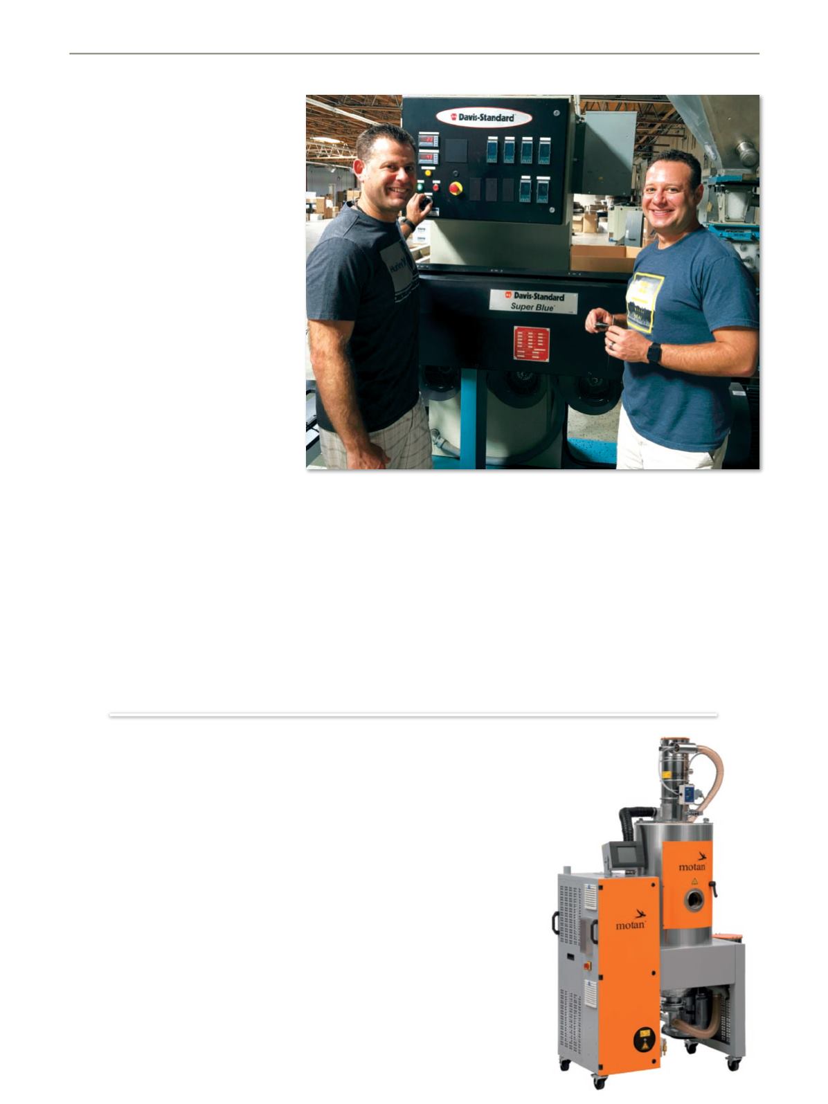
www.davis-standard.com/aftermarketDavid Sacks (left) and Jonathan Sacks (right), co-owners of Tempo Products,
with the Davis-Standard extruder that is back to optimal production rates
thanks to a new feedscrew
ders that come in before 4 p.m., thus the
importance of consistent, high-rate pro-
duction. The newly installed feedscrew is
a replica of the previous screw except
with a harder finish.
“We got a lot of mileage out of the first
feedscrew, and are grateful Davis-
Standard was able to accommodate this
rushed delivery. We definitely plan to do
more frequent feedscrew and barrel
checks to avoid this issue in the future,”
added Sacks.
Davis-Standard offers a complete line of
aftermarket services to support feed-
screw and barrel efficiency. Factors to
consider include feedscrew, barrel and
drive alignment, barrel heating uniformi-
ty, materials being processed, improper
barrel support and corrosion. Periodic ins-
pections at 90- to 180-day intervals are
recommended. The two primary me-
thods for evaluating feedscrew output
loss include the accurate method and ap-
proximation method. The accurate me-
thod compares current screw output with
production benchmark output, which is
established upon feedscrew installation.
The approximation method involves mea-
suring the feedscrew, calculating the re-
sultant added screw-to-barrel clearance
and estimating the output loss from the
added clearance. This technique requires
approximately 24 hours of downtime
while the feedscrew is being removed,
cleaned and measured.
Following are the guidelines when using
the approximation method. A measure-
ment of .010 to .015 inches (.25 to
.38mm) plus the original feedscrew and
barrel clearance is indicative of wear, but
the condition is not critical. A measure-
ment of .020 to .030 inches (.5 to
.76mm) plus the original screw and bar-
rel clearance indicates feedscrew or bar-
rel replacement should be considered.
When the measurement reaches .040 to
.050 inches (1 to 1.3mm), this is severe
wear and it is essential to replace the
feedscrew or barrel, or both.


